Why Do Wind Turbines Spin So Slowly?

Wind turbine blades can look slow while their tips move rapidly through the air. Why doesn't spinning faster always make more electricity?
Follow the explanation from blade-tip speed and aerodynamic forces to pitch and torque control, a geared drivetrain, electromagnetic induction, power electronics and direct drive. The useful speed depends on the wind, the blade design and the machine's operating limits.
This article is the full narration of the video. Watch on YouTube
The slow-looking turn
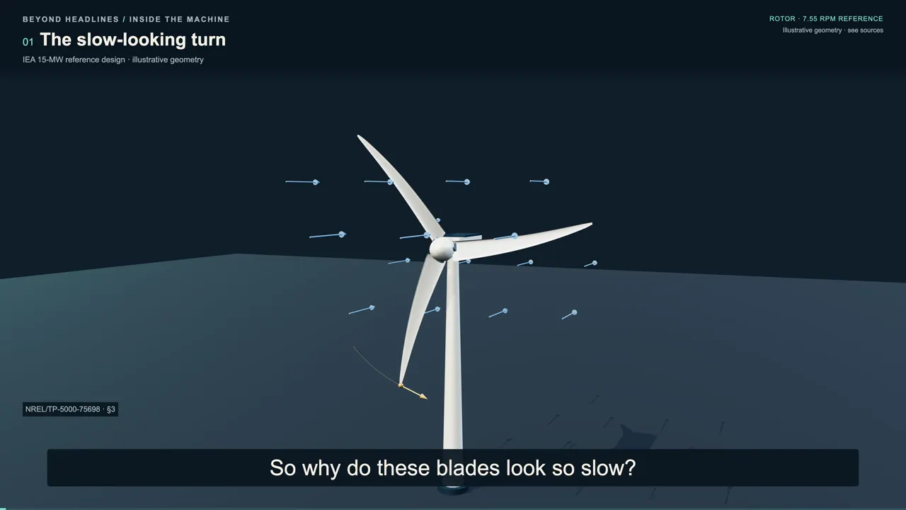
Wind turbines are built to catch the wind. So why do these blades look so slow? Wouldn't spinning faster make more electricity? Here's the surprise: a slow-looking turn can send the blade tips racing through the air.
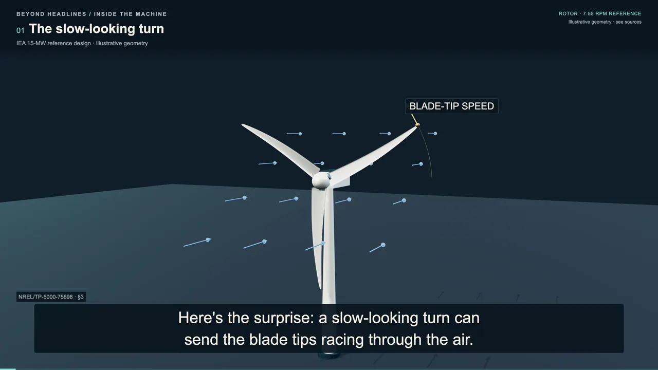
And faster isn't always better. The useful speed depends on the wind, the blade design, and what the machine can safely handle.
A fast tip on a slow rotor
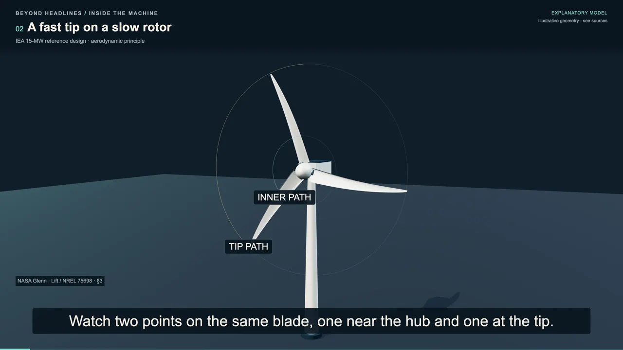
Watch two points on the same blade, one near the hub and one at the tip. They complete each turn together, but the tip travels a much longer path in that same time. For a concrete example, take the IEA fifteen-megawatt reference turbine, a research design published in 2020. Its rotor is 240 meters across, and its rated rotation is about seven and a half turns per minute.
With a radius of 120 meters, that rotation sends the tip through the air at about 95 meters per second. The low number of revolutions describes a huge circle, hiding a fast-moving tip. Now move alongside a small section of blade and consider the airflow it encounters. That relative airflow combines the incoming wind with the blade's own motion, so it approaches the moving section at an angle.
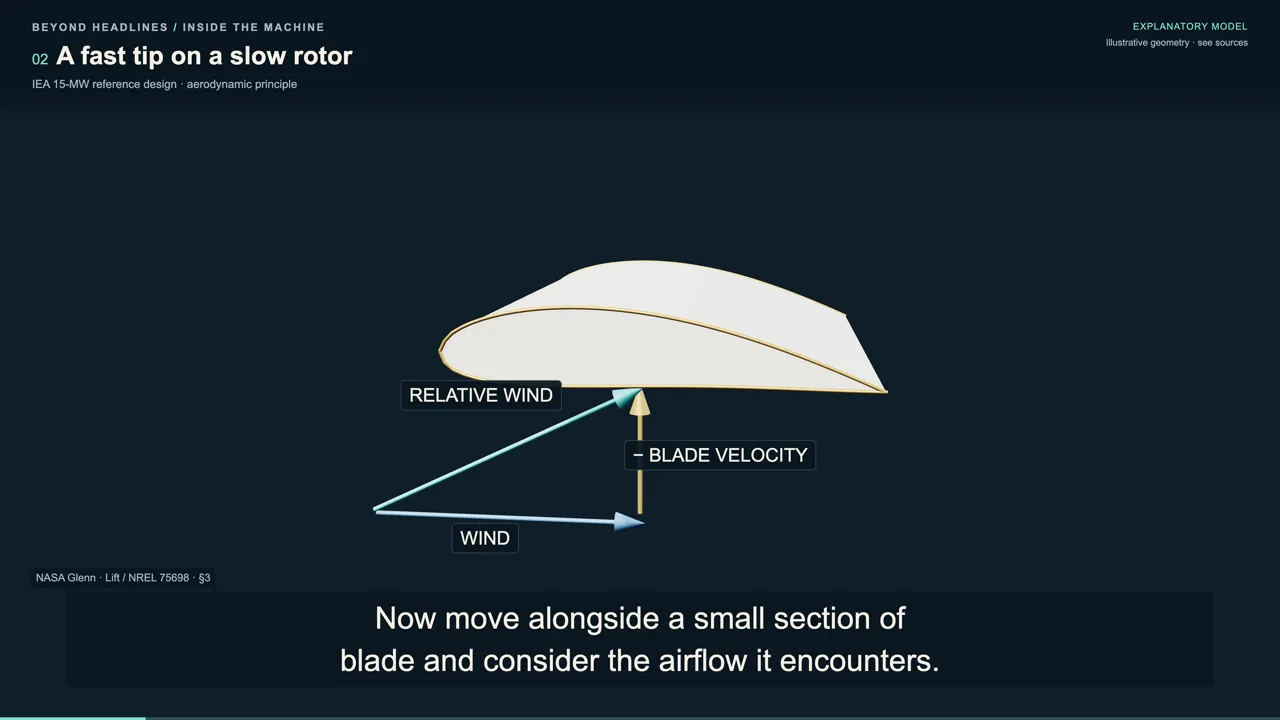
The airfoil shape develops lift across that relative airflow, while drag acts along it. Part of the resulting aerodynamic force acts in the direction of rotation, pushing the blade around and turning the hub. Another component loads the rotor in the direction along its axis, where the structure must carry it. Changing the blade's speed or angle changes the airflow it encounters, and therefore changes both the turning force and the loads.
Finding the useful speed
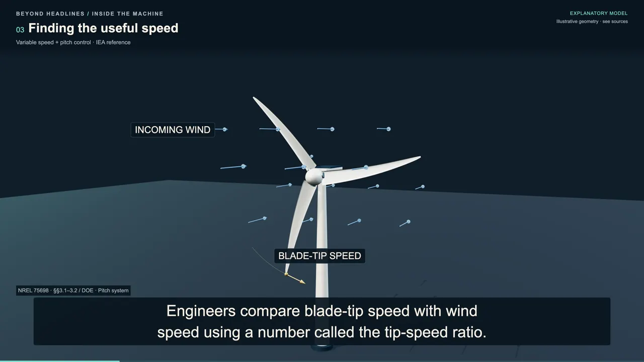
Engineers compare blade-tip speed with wind speed using a number called the tip-speed ratio. If the tip moves nine times as fast as the incoming wind, the ratio is nine, regardless of the units used. For a given blade design and pitch setting, there is a useful operating region for capturing energy from that flow. Increasing rotation can move the rotor toward that region, but continuing to increase it can move the rotor away again.
The ratio alone doesn't prescribe the best setting for every turbine. The IEA reference design distinguishes its chosen operating point from the setting with the highest aerodynamic power coefficient, because it also has to respect its loads. In the reference design's main region below rated wind speed, generator torque control regulates rotation toward the chosen tip-speed ratio.
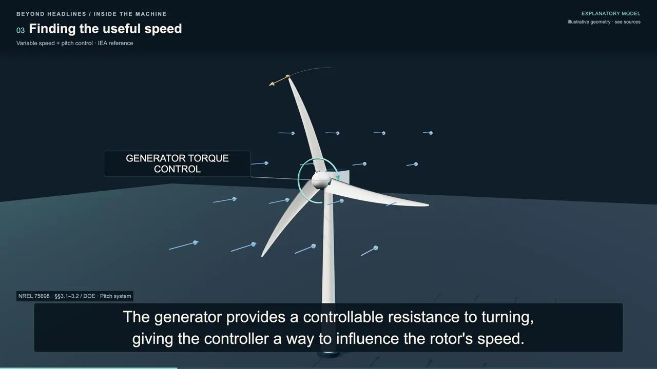
The generator provides a controllable resistance to turning, giving the controller a way to influence the rotor's speed. At lower wind speeds, this design also maintains a minimum rotor speed, so its control strategy changes. Even before rated power, a practical turbine has limits that keep it from following one ideal ratio under every condition. Once the reference turbine reaches rated conditions, blade pitch control regulates its rotation near the rated speed.
Turning the blades about their long axes changes their angle to the airflow, allowing the machine to limit how much power it takes. The blades and tower must also withstand loads, and bending blades must retain clearance from the tower. The controller works within those design limits; a stronger wind does not mean rotation and electrical output should keep rising without a limit.
Trading torque for speed
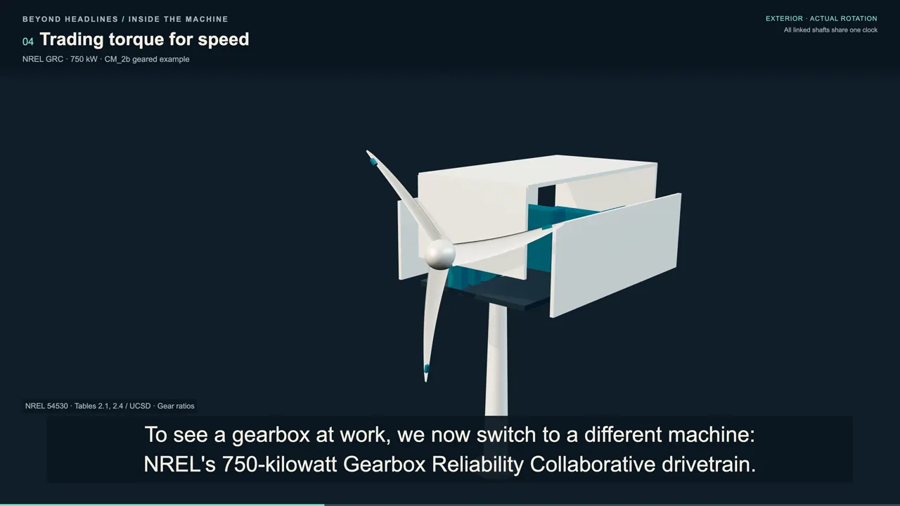
To see a gearbox at work, we now switch to a different machine: NREL's 750-kilowatt Gearbox Reliability Collaborative drivetrain. This older reference uses two nominal generator speed modes, so its mechanism is separate from the variable-speed IEA design. Follow the main shaft from the hub into the gearbox, where one planetary stage feeds two parallel stages. At the selected test condition, the main shaft turns about 22 times a minute while the generator shaft turns about eighteen hundred.
Across the whole gearbox, the output makes about 81 and a half turns for each turn of the input. The final pair alone makes a four-to-one change, with an 88-tooth gear driving a 22-tooth pinion. As those teeth pass through their shared contact, the smaller gear must make more revolutions to keep up. That relationship sets their speed ratio, and the connected stages multiply their ratios along the path to the generator.
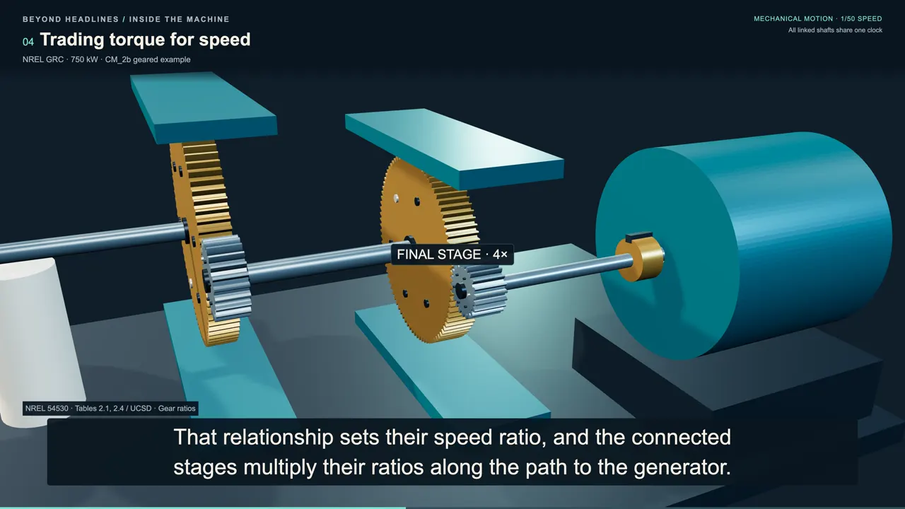
Mechanical power depends on torque multiplied by angular speed, so the faster shaft doesn't imply extra power created inside the gearbox. In the ideal steady transfer, increasing speed means reducing torque in proportion, while preserving the power being transmitted. A real gearbox has frictional losses, so the mechanical power reaching its output is lower than the power entering it. The speed increase helps match the rotor to a faster-running generator, which can be smaller than a low-speed generator.
We have slowed this mechanism for observation, while keeping the connected shafts on the same clock. The gear ratio explains their different turning rates; the next question is how the generator converts the transmitted mechanical power into electrical power.
The electrical handoff
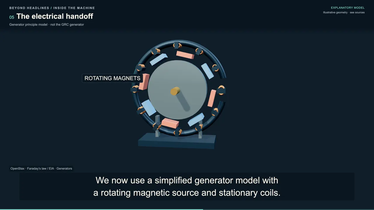
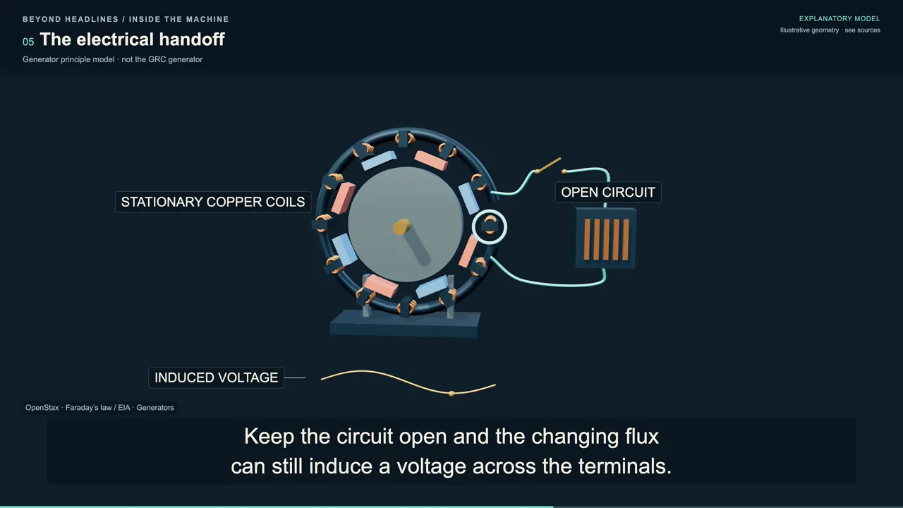
We now use a simplified generator model with a rotating magnetic source and stationary coils. This isolates electromagnetic induction without treating the drawing as the construction of the GRC generator. Watch the magnetic field through one coil as the magnetic source turns past it. The magnetic flux through that coil changes, and Faraday's law relates that rate of change to the voltage induced in the coil.
In this simple rotating model, the flux rises and falls through the turn, and the induced voltage changes direction. The voltage follows how quickly the flux is changing, so its peaks do not occur where the flux itself reaches its peaks. Keep the circuit open and the changing flux can still induce a voltage across the terminals. In our ideal open circuit, there is no current delivered to the load, so that voltage alone does not show useful electrical power being transferred.
Close the circuit through a load, and current can flow as the generator transfers energy into it. That current creates a magnetic response opposing the change that produced it, giving the generator an electromagnetic resistance to being turned. The shaft must keep supplying mechanical work against that resistance to sustain the electrical transfer. This is the connection between torque and generation: the rotor's turning force supplies the energy,
while the generator and connected circuit determine how it is taken.
From generator to grid
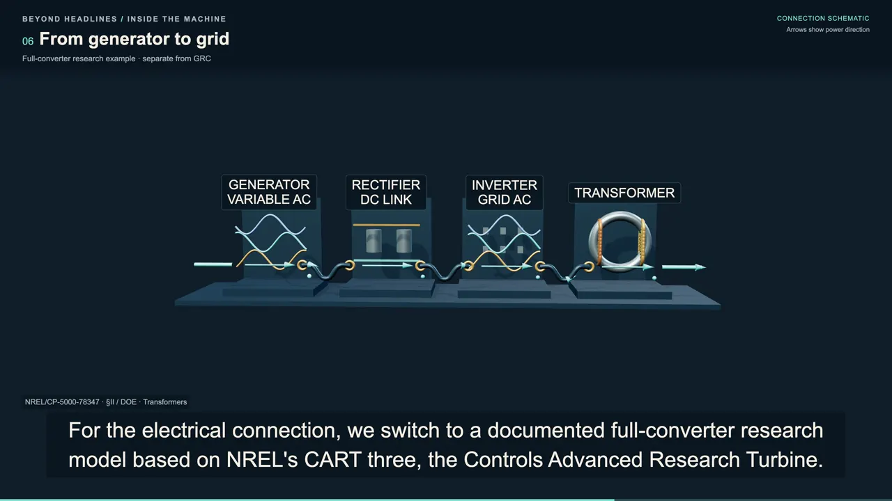
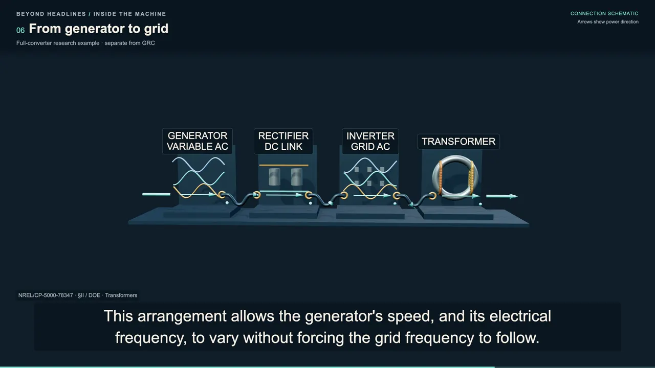
For the electrical connection, we switch to a documented full-converter research model based on NREL's CART three, the Controls Advanced Research Turbine. Here, power electronics provide an interface between the generator's variable operation and the alternating-current grid. In the reported model, a rectifier converts generator alternating current into direct current, which passes through a DC link. An inverter then converts that direct current into controlled alternating current at the grid frequency.
This arrangement allows the generator's speed, and its electrical frequency, to vary without forcing the grid frequency to follow. In the basic converter arrangement, the grid-side converter manages DC-link voltage and the power exchanged with the grid. A transformer performs a different job by changing the voltage of alternating-current electricity. Raising transmission voltage reduces the current required to carry power, helping reduce the losses in the lines that take electricity away from a wind plant.
The plant's electrical network gathers the turbines' output and connects it through a substation to the wider grid. The generator, converter, and transformer each handle a different part of that transfer, after the wind has already supplied the mechanical energy.
Taking out the gearbox
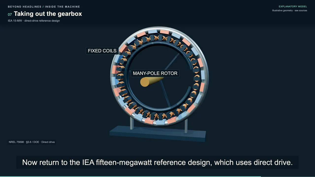
Now return to the IEA fifteen-megawatt reference design, which uses direct drive. Its rotor connects to the generator without a speed-increasing gearbox, so the generator must work at the low rotational speed of the wind rotor itself. The reference generator has a ring of permanent magnets on its rotating outer part, surrounding a stationary structure carrying coils. Its many magnetic poles let a slow mechanical turn produce repeated magnetic changes as those poles pass the coils.
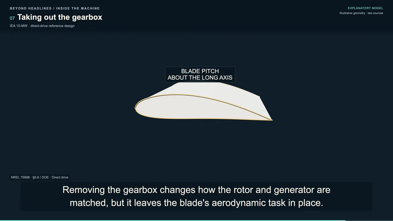
Removing the gearbox changes how the rotor and generator are matched, but it leaves the blade's aerodynamic task in place. This direct-drive design still uses torque and pitch control to capture energy within the rotor's operating limits. Gearbox layout describes the mechanical connection, while converter layout describes the electrical connection. They answer different questions about the turbine, and looking at a slow rotor alone cannot tell us which complete drivetrain and electrical system is behind it.
Reading the rotor again
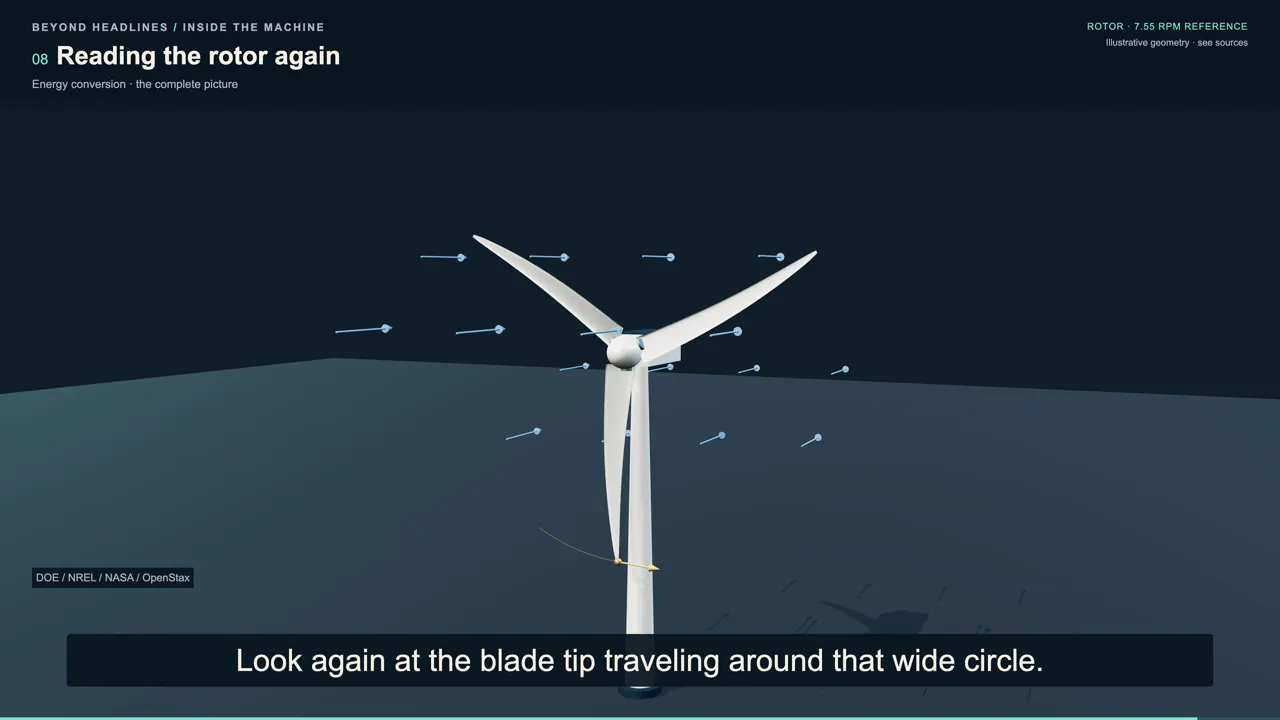
Look again at the blade tip traveling around that wide circle. A rotor can make only a few turns per minute while its tips move rapidly, because each revolution carries them such a long distance. Spinning faster helps only when it moves the machine toward a useful operating condition within its limits. The amount of power also depends on the turning torque and on how the generator and electrical system transfer that energy.
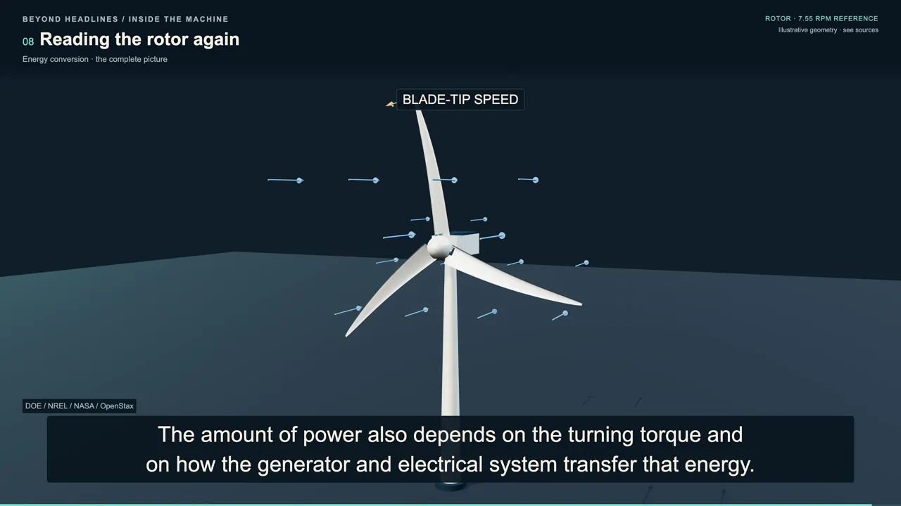
Those slow-looking turns are part of a controlled exchange between moving air and the electrical network. The controller can change blade pitch and generator torque as the wind changes, keeping the rotor working inside the range it was designed to use.
Watch on YouTube
Sources
- S1 — DOE, How Do Wind Turbines Work? https://www.energy.gov/cmei/systems/how-do-wind-turbines-work
- S2 — NASA Glenn, Lift https://www1.grc.nasa.gov/beginners-guide-to-aeronautics/lift-3/
- S3 — NREL/TP-5000-54530, Wind Turbine Gearbox Condition Monitoring Round Robin Study – Vibration Analysis https://docs.nlr.gov/docs/fy12osti/54530.pdf
- S4 — UCSD MAE3, Gear Ratios https://mae3.eng.ucsd.edu/machine-design/gear-ratios
- S5 — OpenStax, University Physics Volume 2 §13.1, Faraday's Law https://openstax.org/books/university-physics-volume-2/pages/13-1-faradays-law
- S6 — DOE, Explore a Wind Turbine — Text Version https://www.energy.gov/cmei/systems/explore-wind-turbine-text-version
- S7 — EIA, How electricity is generated https://www.eia.gov/energyexplained/electricity/how-electricity-is-generated.php
- S8 — NREL/CP-5000-78347, Integration of Storage in the DC Link of a Full Converter-Based Distributed Wind Turbine https://docs.nlr.gov/docs/fy21osti/78347.pdf
- S9 — NREL/TP-5000-75698, Definition of the IEA Wind 15-MW Offshore Reference Wind Turbine https://docs.nlr.gov/docs/fy20osti/75698.pdf
- S10 — DOE Small Wind Guidebook https://www.energy.gov/cmei/systems/windexchange/small-wind-guidebook
- S11 — OpenStax, University Physics Volume 2 §13.2, Lenz's Law https://openstax.org/books/university-physics-volume-2/pages/13-2-lenzs-law
- S12 — NREL/TP-5000-81338, Advanced Distributed Wind Turbine Controls Series: Part 1 — Flatirons Campus Model Overview https://docs.nlr.gov/docs/fy22osti/81338.pdf